

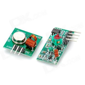
My first idea was to get Mia Robocat to be able to turn lights on and off, turn appliances like television on as well as change channels. So I bought the following 433MHz rf receiver and transmitter which are very cheap (about £2).
To be honest I had to do quite a bit of reading around the subject on the internet. Some of the resources can be found at Stavros’ Stuff and Princetonics. I then proceeded to connect the transmitter and receiver to my mini arduino on the robocat. Part of the reason for this is that the arduino can utilize 5v for the receiver whereas the Raspberry Pi will fry on that voltage level. Using the code from the Home Easy project I was able to grab the codes from the Nexa remote control and fire them off to turn the nexa sockets on and off. But the main problem with this was the programming space on the arduino. I couldn’t use the arduino to run the robocat motors as well as receive and transmit 433rf signals so the project went on the backburner for a while.
I got back to this project after getting the pizero free from the magazine MagPi. I proceeded to solder on the pins and got back re-reading the stuff around Home Automation. Why I decided to write my own program was that all the things I could find available on the internet weren’t exactly what I needed. Some were too specific to the arduino rather than the Raspberry Pi. Many were very specific to one kind of switch and most concentrated too much on transmitting rather than receiving. I had by now got a Blyss wireless doorbell which I wanted to capture and play my own tunes rather than the provided ding-dong.
Luckily I found a very good tutorial at Instructables which I recommend. Not only does it explain clearly, but it also gives the code in Python which is much easier to understand than most languages. My work started where this finishes really. Source code and instructions can be found here.
I would recommend to anyone who wants to do things with the gpio pins of the raspberry pi to install wiringPi. One of the problems is that the numbering of the pins across the web is really inconsistent and left me scratching my head a lot. If you run the following command gpio readall it will give you a map of the pin numbering for your version of the Pi.
pi@raspberrypi ~/RF433Ctrl $ gpio readall
 +-----+-----+---------+------+---+---Pi 2---+---+------+---------+-----+-----+
 | BCM | wPi |   Name  | Mode | V | Physical | V | Mode | Name    | wPi | BCM |
 +-----+-----+---------+------+---+----++----+---+------+---------+-----+-----+
 |     |     |    3.3v |      |   |  1 || 2  |   |      | 5v      |     |     |
 |   2 |   8 |   SDA.1 |   IN | 1 |  3 || 4  |   |      | 5V      |     |     |
 |   3 |   9 |   SCL.1 |   IN | 1 |  5 || 6  |   |      | 0v      |     |     |
 |   4 |   7 | GPIO. 7 |   IN | 1 |  7 || 8  | 1 | ALT0 | TxD     | 15  | 14  |
 |     |     |      0v |      |   |  9 || 10 | 1 | ALT0 | RxD     | 16  | 15  |
 |  17 |   0 | GPIO. 0 |   IN | 0 | 11 || 12 | 0 | IN   | GPIO. 1 | 1   | 18  |
 |  27 |   2 | GPIO. 2 |   IN | 0 | 13 || 14 |   |      | 0v      |     |     |
 |  22 |   3 | GPIO. 3 |   IN | 0 | 15 || 16 | 0 | IN   | GPIO. 4 | 4   | 23  |
 |     |     |    3.3v |      |   | 17 || 18 | 0 | IN   | GPIO. 5 | 5   | 24  |
 |  10 |  12 |    MOSI |   IN | 0 | 19 || 20 |   |      | 0v      |     |     |
 |   9 |  13 |    MISO |   IN | 0 | 21 || 22 | 0 | IN   | GPIO. 6 | 6   | 25  |
 |  11 |  14 |    SCLK |   IN | 0 | 23 || 24 | 1 | IN   | CE0     | 10  | 8   |
 |     |     |      0v |      |   | 25 || 26 | 1 | IN   | CE1     | 11  | 7   |
 |   0 |  30 |   SDA.0 |   IN | 1 | 27 || 28 | 1 | IN   | SCL.0   | 31  | 1   |
 |   5 |  21 | GPIO.21 |   IN | 1 | 29 || 30 |   |      | 0v      |     |     |
 |   6 |  22 | GPIO.22 |   IN | 1 | 31 || 32 | 0 | IN   | GPIO.26 | 26  | 12  |
 |  13 |  23 | GPIO.23 |   IN | 0 | 33 || 34 |   |      | 0v      |     |     |
 |  19 |  24 | GPIO.24 |   IN | 0 | 35 || 36 | 0 | IN   | GPIO.27 | 27  | 16  |
 |  26 |  25 | GPIO.25 |   IN | 0 | 37 || 38 | 0 | IN   | GPIO.28 | 28  | 20  |
 |     |     |      0v |      |   | 39 || 40 | 0 | IN   | GPIO.29 | 29  | 21  |
 +-----+-----+---------+------+---+----++----+---+------+---------+-----+-----+
 | BCM | wPi |   Name  | Mode | V | Physical | V | Mode | Name    | wPi | BCM |
 +-----+-----+---------+------+---+---Pi 2---+---+------+---------+-----+-----+
 pi@raspberrypi ~/RF433Ctrl $
The project consists of two parts really. A toolkit which should make it easy to track down the codes sent from the 433rf device. Given that there is plenty of noise it is sometimes difficult to see the wood for the trees. The toolkit simplifies by smoothing and clustering the message and plots the code so you can visually see what it is doing. The full list of parameters are below.
           -rec      will record raw signals from 433mhz receiver
           -read      will read values from file
                     use - for default filename
           -write     option to write the values to file
                     use - for default filename
           -trim     will remove low signal at the beginning and
                     smooth out signals of less than 20u
           -mean     works out the mean signal values and applies
                     across the signal thereby rationalizing
           -block    will attempt to find repeating blocks
           -display  displays signal lengths in ms as /HIGH\ and _LOW_
           -plot     alternatively plots the values to graph
To get started I would use the option sudo python toolkitRF433.py -rec -display to get a feel for things and see that you are getting some signal through. Then use gksudo — python toolkitRF433.py -rec -plot to see where you are getting the signal amongst the noise. Then add the -write – option and run either of the previous commands again. If you have a fairly clean signal – you should see several blocks in the middle of the graph then press Y to confirm saving. Then instead of the -rec option use -read – to read the signal from the saved file. Then you could use -block option which will also run the -trim and -mean options and if you are lucky you will get a clean consistent small block of signal consisting of a latch followed by codes representing 1s and 0s. At any point you can edit the receive.dat file manually to cut out noise and repeating blocks.
Once you have captured the protocol of the message you can then enter this protocol json file provided and then by using the receiveRF433Ctrl.py you can listen out for codes of this type. This works for both Nexa and Blyss at present.
I also need to change to 5v as the receive range on 3.3v is too short. I can see that there may be efficiency issues as the receiver would need to be on constantly. I am hoping in future to convert it to an interrupt based approach as described here.
The latest version now includes transmitRF433Ctrl.py which can transmit using the protocol defined. It uses homeautomation.json which defines the sockets.

April 10, 2017 at 7:43 pm
Hi,
i am very interested by this article.
i have at home a hot (for winter time) or cool (summer time) system.
Each rooms has a remote control (with a zone number)
Do you think i will be able to catch the RF Signals “on” or “off” from one RF remote to be able to reproduce it with pi ?
I heard that some remote control use rolling codes that can’t be reproduce with pi.
Do you know how can i know if my remote use rolling code or not ?
Thanks for your help.
LikeLike
April 17, 2017 at 5:26 pm
Hi Dierickx.
Sorry for the delay in replying. I haven’t heard of systems that use rolling codes except for car keys. They use a different pseudo random number each time, but the clever thing is that both the key and the car are seeded with the same initial number so that they each produce the same number each time. If the number isn’t recognized the car will check a few numbers in advance in case the key was pressed our of range.
Outside of security issues like this I haven’t heard of systems that use rolling codes and there is no way of knowing unless someone has tried already. BTW what is the system called.
You should be able to pick the signals up and reproduce with the pi. However be aware of the range issues. My suggestion would be to catch the signals at close range and then use the Pi to send the signals out. Create a web page on your pi and connect through your phone to control the system.
Let me know how it goes,
Dani
LikeLike
January 30, 2018 at 5:36 pm
Nice summary. Finaly succeeded capturing codes from my Nexa remotes, following your instructions. Did you end up doing the transmitter code as well?
Arnto
LikeLike
January 30, 2018 at 9:28 pm
Thanks for your kind comments. No I haven’t done the transmitter yet, but I’ll try and get it done this weekend.
LikeLike
March 2, 2018 at 6:03 pm
I’m trying this out for an Aleko gate opener. basically the boards are no bueno. So I am going to replace the board with a Polulo controller, a raspberrypi a 433Mhz receiver and a few other things. my goal is to replicate the same function as the original board, but be compatible with any 433 or garage remote. that way I can have for example a friend click on his remote for his house and have it be learned on my gate so he can use it for when he visits.
LikeLike
March 2, 2018 at 9:16 pm
That all sounds feasible. You would need to work out the protocol of each different 433 garage remote you are going to cater for. Then get the specific code for the remotes you want. Sounds a great project. Hope my stuff here will be of use.
LikeLike
December 20, 2018 at 7:03 pm
Thank you for the tutorial. I am trying to get data from a weather station. With sudo python toolkitRF433.py -rec -display I see can see data.
sudo python receiveRF433Ctrl.py however, does not return any results. I guess the reason is a missing protocol in the json file. So I would like to add an entry for my weather station works with this protocol: https://manual.pilight.org/protocols/433.92/weather/alecto_ws1700.html
Could you provide any hint on howto fill in the parameters in the json file for this protocol?
LikeLike
December 20, 2018 at 10:02 pm
Hi Markus. Thanks for showing interest in this project. On the face of it this looks straight forward to set up the protocol. If you use the nexa one as an example. I’ll assume that the first pulse is high. You would set the latch as the first eight pulses 540 1890 540 3780 540 1890 540 3780 so that is
{
“Signal”:1,
“Length”:540
},
{
“Signal”:0,
“Length”:1890
},
{
“Signal”:1,
“Length”:540
},
{
“Signal”:0,
“Length”:3780
}
etc
Set the number of bits to 36. Next decide which of these will be 0 and which 1. 540 1890 or 540 3780. It doesn’t matter which you choose. Then put these values into the timings
“value”:0,
“timings”:[
{
“Signal”:1,
“Length”:540
},
{
“Signal”:0,
“Length”:1890
}
etc
Don’t forget the ending which seems to be 540 9180.
That should do it. The one thing that is confusing is the values 4050 which the description doesn’t mention. If that is indeed what is returned you may need to up the value of 3780 and adjust the tolerance – it will depend on the values you actually get back. Hope that helps. If you still have problems send me the data from the toolkit.
LikeLike
January 3, 2019 at 11:45 pm
Thanks for the hints. However, I still cannot get the script to work. I recorded about 80 seconds since I expect at least one temperature signal per minute. A histogram (number of counts vs pulse duration) can be found here:
https://imagebin.ca/v/4SHz8q45eonT
Does this help in any way? The protocol.json : https://pastebin.com/whhrwQVe
LikeLike
January 8, 2019 at 10:32 pm
hi markus (weather.15.mage@spamgourmet.com),
The protocol looks ok to me but not the image pasted. I can’t make out anything. what you should see is something like this.
Vertical is high 1 and low 0 signal and horizontal is duration. Combinations of high and low signals signify code 1 or 0. Your system may be using the actual signal strength but even that doesn’t correspond to the protocol values. If I get a chance I’ll do a bit of digging on the internet to see if anyone else has done something similar.
Dani
LikeLike
January 8, 2019 at 10:56 pm
Hey Dani, I did some more analysis. If I record the signal to a file (csv, because I am more used to work with numpy arrays) and run the expected header timings in a loop across the recorded timings, I do actually get temperature signals! One of them looks like this (including footer):
[ 545. 1860. 463. 3816. 486. 1859. 494. 3806. 492. 3818.
490. 3818. 465. 1858. 487. 3818. 495. 1859. 494. 1860.
494. 1852. 494. 3819. 494. 3847. 238. 1840. 502. 1861.
491. 1860. 491. 1861. 488. 1858. 494. 1860. 494. 1861.
493. 3810. 467. 3819. 493. 3801. 495. 1862. 500. 1883.
499. 3817. 451. 3818. 508. 1856. 513. 1852. 507. 1859.
498. 1867. 497. 3825. 502. 1868. 467. 1856. 510. 3816.
497. 1869. 491. 9138.]
[ 0. 1. 0. 1. 1. 1. 0. 1. 0. 0. 0. 1. 1. 0. 0. 0. 0. 0.
0. 0. 1. 1. 1. 0. 0. 1. 1. 0. 0. 0. 0. 1. 0. 0. 1. 0.]
230.0 <- That temperature is identical to the display of the station (needs to be divided by 10)
If I run the receive script on the other hand and have "TheNumber" printed I get a block like this every 30 seconds which seems to be the frequency of update by the weather station:
returning no. 00000
returning no. 0100100100
returning no. 01110101100000001110011000010010
returning no. 1011101000110000000110011000010010
returning no. 0101111000110000000111001100001001
returning no. 01011010001100000001110010000100
returning no. 0010111010001100000001110011000010
returning no. 10010101000110000000111001100001
However, none of the numbers is long enough to have 36 bits. I am wondering when def __ReadDigits(self,protocol) starts taking the first bit in a data stream. I would imagine that if it starts at random, it may start within an actual valid 36-bit code but not at the beginning of it.
LikeLike
January 10, 2019 at 9:48 pm
Hi Marcus. I think you are fairly close to cracking it. The way it works is that it will start reading and try and match the header. If it doesn’t then it will bomb out and start reading again. Only if it matches the header will it go on to match the digits so it should always start at the beginning of the number. If it doesn’t get the correct number of digits it will also bomb out. There may be noise which messes things up. For some reason you are dropping digits. If these digits line up you should see the correlation. The last two numbers you gave are slightly strange but otherwise.
– -0111010- -1100000001110011000010010
010111010001100000001110011000010010 – this is the correct value
-101110100011000000011- 0011000010010
010111-1000110000000111001100001001 –
01011-01000110000000111001-0000100 – –
Perhaps check the timings coming back in for spikes which may not be read correctly. You may need to adjust the tolerance in that case.
Dani
LikeLike
January 11, 2019 at 11:43 pm
I think the problem is probably that my header is [540, 1890, 540, 3780, 540, 1890, 540, 3780] -> 8 pairs as opposed to 1 pair in each of the examples given in the json files. The getLatch function reads the first pair of the header stream. Afterwards ReadDigits would see 7 header pairs and 28 digit pairs (and 1 footer pair). Since the number of bits is set to 36, the 36th pair is the footer pair which is consequently not recognized as a digit because it does not match the digit timing.
When I change the number of bits to 35 (=latch bits + digit bits -1), then I get actual numbers 🙂
LikeLike
January 13, 2019 at 8:22 pm
Hi Markus. It looks like you have cracked it. If you have a final protocol file, could you send it to me and I can make it available on the bitbucket site for others to use in the future. Only if you are happy to do that. Thanks Dani
LikeLike
January 14, 2019 at 9:19 pm
I am very happy to do so:
https://pastebin.com/JW3azsgx
Up next, I have two more stations to crack 😉
One is supposed to have this protocol: https://github.com/merbanan/rtl_433/blob/master/src/devices/rubicson.c
and the other one
https://github.com/merbanan/rtl_433/blob/master/src/devices/infactory.c
However, the first description talks about hexadecimal(?) numbers like 0x6c. I guess I need to translate this to binary numbers and apply a similar scheme as before?
LikeLike
January 16, 2019 at 8:56 am
First thing is to work out what timings mean 0 and 1 (which I can’t immediately see). Other than that you can convert binary to hex by changing the line print int(number,2) to print hex(int(number,2))
LikeLike
January 18, 2019 at 10:10 pm
Hello, thank’s for the tutorial, I don’t understand how to read my signal.
I stayed pushed on the button all the time.
first : zoom in on 2 repeated pattern
second image : all the plot
thank for help
LikeLike
January 19, 2019 at 10:59 am
Hi Giuseppe. The good news is that you are definitely getting a signal back and there is a definite repeatable pattern. However it doesn’t seem to be a binary code. If you think of it the binary number is only a shorthand for blasts of high and low signals for different lengths of time. What your approach should be depends to some extent on what you are trying to achieve. First of all what switches are you using. Secondly are you only trying to read the signal or are you hoping to copy it and simulate it with the Raspberry pi?
LikeLike
January 19, 2019 at 11:31 am
Hi, thanks for the quick response.
I want to simulate it with the raspberry.
It was the button up of my roller shutter, all the button have similar patterns with strange signal.
I don’t know what I need to do after that.
Thanks for help
LikeLike
January 19, 2019 at 11:33 am
I would want to close all my roller shutter and open it back with one button on my phones or with Alexa (I have 3 of them).
I just need to send this signal back with my 433 transmitter.
LikeLike
January 19, 2019 at 12:03 pm
Out of interest what is the make of the roller shutter system. The other thing is how does the code differ between opening and closing. Is the same code?
There are two possible approaches you could take. First of all take one key press block. Within that block how many identifiable patterns are there. There is the first pattern repeated 5 times plus a few other types. call each of these a number say 1 to 5 and timings for each of these. This will give you your code eg. 11111223220. When trying to repeat this you go through each digit and use the timings associated with each digit. This was done by Daniel Becker who had a similar system for a dorma garage door opener.
import time
import sys
import RPi.GPIO as GPIO
a_on = ‘1010221332101’
a_off = ‘1111111111111010101010111’
b_on = ‘1111111111101110101011101’
b_off = ‘1111111111101110101010111’
c_on = ‘1111111111101011101011101’
c_off = ‘1111111111101011101010111’
d_on = ‘1111111111101010111011101’
d_off = ‘1111111111101010111010111’
short_on = 0.000381
short_off = 0.0003815
long_on = 0.000910
long_off = 0.00011203
extended_delay = 0.0096
NUM_ATTEMPTS = 10
TRANSMIT_PIN = 23
def transmit_code(code):
”’Transmit a chosen code string using the GPIO transmitter”’
GPIO.setmode(GPIO.BCM)
GPIO.setup(TRANSMIT_PIN, GPIO.OUT)
for t in range(NUM_ATTEMPTS):
for i in code:
if i == ‘1’:
GPIO.output(TRANSMIT_PIN, 1)
time.sleep(short_on)
GPIO.output(TRANSMIT_PIN, 0)
time.sleep(short_off)
elif i == ‘0’:
GPIO.output(TRANSMIT_PIN, 1)
time.sleep(long_on)
GPIO.output(TRANSMIT_PIN, 0)
time.sleep(long_off)
elif i == ‘2’:
GPIO.output(TRANSMIT_PIN, 1)
time.sleep(short_on)
GPIO.output(TRANSMIT_PIN, 0)
time.sleep(long_off)
elif i == ‘3’:
GPIO.output(TRANSMIT_PIN, 1)
time.sleep(long_on)
GPIO.output(TRANSMIT_PIN, 0)
time.sleep(short_off)
else:
continue
GPIO.output(TRANSMIT_PIN, 0)
time.sleep(extended_delay)
GPIO.cleanup()
if __name__ == ‘__main__’:
for argument in sys.argv[1:]:
exec(‘transmit_code(‘ + str(argument) + ‘)’)
The other way you could do it is to just put the timings in one list and then just blast them out.
Hope this helps.
LikeLike
January 24, 2019 at 9:58 pm
Alright, next station seems to be running. A kwmobile weather station with temperature and humidity. The data stream is
[500 3800] header
72 values (36-bit) body
[500 3800] footer
I am not sure about header and footer though. The stream is sent multiple times so the footer might already be the next header but I can work with that.
Temperature is body digits 12 to 23 multiplied by ten. Humidity is digits 28 to 35 (assuming indexing of body starts at digit 0)
json:
https://pastebin.com/AF6tgC78
LikeLike
April 12, 2019 at 12:32 am
Hello, I’m pretty new to raspberry pi and 433mhz, sorry if this is dumb. I’ve got two signals I want to control, I have a door bell that I want to implement into MQTT, so I want to send a MQTT messege when I get a signal from the push button. I’ve managed to read it’s signal with RC-Switch on arduino and got the following back: https://pastebin.com/2HW7eTmN
Now, how would I go about adding it into the json, and making a script looking only for that signal?
I know it’s a big question, but if you could atleast point me in the right direction I would highly appriciate it!
I also have some Nexa sockets, I beleve it’s the same one you have, the remote is a PET-910 and sockets are PER-1500.
I can see the signal with receiveRF433Ctrl.py, and get the following for Socket 3 ON: 807018642 OFF: 807018626
I’ve tried to send the signal with ./_433D(pigpio), 433Utils and send.py(rpi-rf). However I cant get it to work. I’ve managed to send the signal to the doorbell speaker and know my transmitter is working.
Any help or pointers are highly appriciated!
LikeLike
April 12, 2019 at 7:55 pm
Hi Alsin and thanks for your interest in my tech blog site.
On the face of it this looks quite straight forward. The timings are pretty much like this
4484 – latch
76,500 – 0
380,196 – 1
If you start from the end of the number it should all make sense. You’ll notice that there are differences and so you should take the mean. You can either do that manually or my toolkit should be able to help you with that. The only thing that isn’t clear for the data is whether it starts with high or low but I would assume that it is high. If you put that in the protocols.json as the only protocol then the recieve script will listen out for that. Let me know how it goes and if you get it working please send me the json and I will add it to the protocols on the bitbucket code.
On the Nexa issue – I have done a transmit python script which might help you. I have also adjusted the timings slightly. I will upload these over the weekend. If you still have problems you need to check that the sockets aren’t out of range and the correct pin etc. You could also use the toolkit and adjust the timings. Ok best of luck and let me know how it goes.
Dani
LikeLike
April 12, 2019 at 10:16 pm
The transmit code has now been uploaded.
LikeLike
April 13, 2019 at 1:00 pm
Hello, thank you so much for your help, I started with the Nexa issue. I’m now able to transmit to my sockets thanks to your script! I wrote a little python script that subscribes to my mqtt broker and runs your script with the values in the payload.
I haven’t had much time looking into the doorbell yet, I still cant fully understand the protocols.json contents(sorry I’m new to this). I tried to run your toolkit script again and managed to isolate the signal I think, here is a image from when I cut out the noise in the beginning: https://i.imgur.com/i2JM3aX.png
So at the moment I’m stuck on what I should set the in the protocols.json file.
I tried to set latch to 4484(tried both signal 0 and 1) body value 0 76,500 and body value 1 380,196, ending empty. This is probably completely wrong I’ve read so much different information on the topic and gotten nowhere, with every site I read from using different methods. Hope you can help.
LikeLike
April 13, 2019 at 2:42 pm
Hi Alsin.
Glad you’ve got the nexa sorted. The signal will have to be high followed by low (or low followed by high) alternatively so once you’ve got the start it shouldn’t be a problem. From what you say that does sound right, but if you want me to have a look over the json file let me know. The bad news however is that this doesn’t seem to correspond at all with the image, though there is definitely a signal being captured. I am a bit baffled about that. According to the figures you send you should see 010100011101111101010100 so there should be a definite double zero at the end and if you look at the raw data it should correspond to the raw data you sent. ie starts with something vaguely like 4484,152,424,396,180 etc. Your signal doesn’t seem to be 24 bits long either.
Dani
LikeLike
April 13, 2019 at 5:11 pm
Hello, thanks again for your help, but I still stuck. The picture I included was only the beginning of a scan I did. I tried again so here are two pictures, the second picture is more zoomed in then the first, so I’ve marked in the first where I zoomed in. https://imgur.com/a/pRIv2sb
To get the scan I first ran ‘toolkitRF433.py -rec -write – -plot’ with the button pressed from when the Start Recording text appears to Stopped. Then I ran ‘toolkitRF433.py -read – -write – -block’ and got no repeating blocks found and typed Y. Then I look at it with toolkitRF433.py -read – -plot
In case it helps here is the recieve.dat file: https://pastebin.com/WFTq3r46
And here are the original RC-Switch scans I did on my arduino: https://pastebin.com/2HW7eTmN
LikeLike
April 13, 2019 at 8:28 pm
I’m afraid I’m still baffled. Could you try and just push the button once very briefly to see if we can isolate it to one instance. The other thing I would be interested to know is what make it is and what the protocol the RC-Switch says it is. ie what is protocol 1 that it mentions. That may clarify because the raw data as it is doesn’t look anything like what rc-switch is showing.
LikeLike
April 13, 2019 at 9:07 pm
The make is Biltema: https://www.biltema.no/hjem/sikkerhet-i-hjemmet/dortilbehor/dorklokke-tradlos-2000032620
Art.nr. 21-950
When I scan with one brief press, I’m unable to see where the signal is in between the noise.
https://imgur.com/a/hH4UuNl I’m pressing the button once briefly, but dont know if it’s before or after the gap in the graph. Here is the unedited receive.dat from this recording if you need: https://pastebin.com/M7tT6Z6A
LikeLike
April 13, 2019 at 9:44 pm
looking up the RC-switch protocols I found the following in: https://github.com/sui77/rc-switch/blob/master/RCSwitch.cpp
{pulselength, Sync bit, “0” bit, “1” bit}
{ 350, { 1, 31 }, { 1, 3 }, { 3, 1 }, false }, // protocol 1
I will try to run the toolkit again with one brief push, but last time I tried I could not see clearly where the signal was in the plot.
LikeLike
April 14, 2019 at 8:46 pm
Sorry I’m still a bit baffled. The plot doesn’t look like the figures. And protocol 1 doesn’t seem to correspond to the raw values. Without a clear idea of the beginning and end it is very difficult to understand the protocol even though there is an obvious repeating pattern. I’ve had a bit of a browse round the internet but unfortunately I can’t see where anybody has done something with this doorbell.
LikeLike
September 10, 2019 at 12:30 am
Greetings
I tried running receiveRF433Ctrl.py but complained abt error in line 45!
There are also missing brackets in two print statements that was picked by the debugger
Any suggestion.
Thank you
LikeLike
September 10, 2019 at 7:29 am
Hi R. Gerges. These are both features that existed and worked in previous versions of Python. If you change line 45 to
if not (number is None) and not(number==”):
Let me know if there are any other issues. I’ll try and get an update done shortly.
LikeLike
September 10, 2019 at 4:52 pm
Dani
Thank you for your prompt response. The program runs now, displays “ Start Recording for 5 seconds” and is stuck there!
LikeLike
September 10, 2019 at 7:20 pm
Hi R. It’s a bit difficult to say from that. You are running the toolkit and using the record option. Does it get to printing out stopped. If not then have you used sudo as the gpio pins require those privileges. Also check that you have the pins set up correctly. Otherwise you will have to narrow it down by putting in print statements until you get to the line of code that is hanging.
LikeLike